

Introduction
Theoretical and Experimental Background
Experimental Apparatus and Procedures
Characteristics of Kaolinite
Design of Experimental Apparatus
Testing Procedure
Electro-Osmotic Pulse System
Results and Discussion
Amount of Dewatering
Temporal Variations in Electric Current
Final pH and Water Content Distribution in the Soil Bed
Conclusions
Introduction
Electro-osmotic dewatering, the application of an electric field to saturated soils, has been studied and practically used under a direct current (DC) electric field (Asadi et al., 2013; Martin et al., 2019). However, during the process of electro-osmotic dewatering under DC conditions, the decrease in water content in a soil bed starts from a position near the electrode opposite the drainage surface and progresses rapidly. Consequently, the electric resistance of the sludge bed is locally increased in the region of the electrode. The electrical contact resistance between the electrode and sludge bed also increases markedly, causing the voltage applied to the bed to fall only in the portion of the bed near the electrode (Yoshida, 1985; Yoshida et al., 1985, 1999; Gopalakrishnan et al., 1996). In such circumstances, the applied electric field does not effectively act throughout the soil bed, and the continuation of the dewatering process gradually becomes more difficult. It may be assumed that the gas produced by electrolysis duringthe dewatering process also adds to the increasing electric resistance. To perform electro-osmotic dewatering efficiently, it is important to reduce such hindrances for dewatering. However, only a few studies (Gray and Somogyi, 1977; Lockhart and Hart, 1988; Rabie et al., 1994) have addressed this problem: Gray and Somogyi (1977) tested electro-osmotic treatment with 30 min electrode polarity reversals for a red mud sample, and Lockhart and Hart (1988) and Rabie et al. (1994) studied electro-osmotic dewatering with interrupted power applications.
This study focuses on improving electro-osmotic dewatering to reduce the influence of the above-mentioned hindrances on the dewatering process. The application of pulse technology with periodic electrode polarity reversals is considered useful for dewatering (Asadi et al., 2013; Martin et al., 2019). By applying a pulse electric field to the soil bed, the water flow in the bed caused by the electro-osmosis is periodically reversed with time, and the sludge bed is dewatered electro-osmotically on both sides of the bed between the electrodes. Consequently, the marked increase in the electrical contact resistance with dewatering may be reduced, producing efficient electro-osmotic dewatering. In this study, the effects of reversal periods on the dewatering rate, dewatered amount, and electric power consumption were investigated experimentally. The results were compared with the results under DC. The study shows the characteristics of electro-osmotic dewatering under pulse application.
Theoretical and Experimental Background
Generally, clay particles have a negative surface charge in the clay-water-electrolyte system. This surface charge can be developed in different ways, including the presence of broken bonds and isomorphous substitution, with cations being electrostatically attracted to clay particles, resulting in cation accumulation close to the surface to satisfy electroneutrality. A number of studies have explored the clay chemistry related to this phenomenon (Sposito, 1984, 1989; Mitchell, 1993; McBride, 1994). The accumulation of cations is opposed by the diffusional force, which tries to equalize the concentration of cations everywhere. Hence, the diffusional force acts in a direction opposite to that of the electrostatic force. Anions in the suspension will experience an electrostatic repulsion by the negatively charged clay surface and a diffusional force in the opposite direction tending to equalize the concentration. This results in the formation of a diffuse cloud of ions surrounding clay particles.
In a dry clay, adsorbed cations are tightly held by the negatively charged clay particles. Cations in excess of those needed to neutralize the electronegativity of the clay particles and associated anions are present as salt is precipitated. When the clay is placed in water, the precipitated salts go into solution. Because the adsorbed cations produce a much higher concentration near the surfaces of particles, they tend to diffuse to equalize concentrations throughout the medium. Their freedom to do so, however, is restricted by the negative electrical field originating in the particle surfaces. The escape tendency due to diffusion and the opposing electrostatic attraction lead to ion distributions adjacent to a clay particle in suspension. The distribution of cations is analogous to that of air molecules in the atmosphere, where the escape tendency of the gas is countered by the gravitational attraction of Earth. Anions, however, are excluded from the negative force fields of the particles.
The charged surface and the distributed charge in the adjacent phase are together termed the “diffuse double layer”. Several theories have been proposed for the quantitative description of ion distributions adjacent to charged surfaces. The Gouy-Chapman theory (Gongadze et al., 2009) of the diffuse double layer has received the greatest attention. Although this theory has been shown to accurately describe the actual distribution of ions only for smectite particles suspended in monovalent electrolyte solutions at low concentrations (Sposito, 1989), it provides a very useful basis for the understanding of flocculation and deflocculation and the relationships of these processes to the formation of soil structure, as well as some aspects of clay compression and swelling.
A mathematical description of the diffuse double layer has been developed for the cases of both planar and spherical surfaces. Only the planar (one-dimensional) case is treated here. The following idealizing assumptions are made:
(1)Ions in the double layer are point charges that do not interact with each other. Although a modification of the theory has been made to account for the finite sizes of the ions, only the theory for point charges is given here.
(2)The charge on the particle surface is uniformly distributed.
(3)The particle surface is a plate that is large relative to the thickness of the double layer (one-dimensional condition).
(4)The permittivity of the medium is independent of position.
The concentration of ions (ions/m3) of type , , in a force field at equilibrium is given by the Boltzmann equation:
where, the subscript 0 represents the reference state, taken to be at a large distance from the surface; is potential energy; is temperature (°K); and is the Boltzmann constant (1.38 × 10⁻²³ J K-1).
For ions in an electric field, the potential energy is
where, is the ionic valence, is the electronic charge (1.602 × 10⁻¹⁹ coulomb), and is the electrical potential at the point. Potential varies with distance from a charged surface. In clays, is negative because of the negative surface charge. The potential at the surface is designated as .
As , because at a large distance from the surface, and the Boltzmann equation becomes
Eq. (3) relates concentration to potential. For negatively charged clay particles, and .
The Poisson equation relates potential, charge, and distance. For the one-dimensional case,
where, is distance from the surface (m), is charge density (C/m3), and is the static permittivity of the medium (C2 J-1 m-1 or F m-1). The charge density in the diffuse layer is contributed by the ions so that
with expressed as ions per unit volume.
Substitution for from Eq. (3) gives
which when substituted into Eq. (4) yields
Eq. (7) is the differential equation for the electric double layer adjacent to a planar surface. Its solution provides a basis for computation of electric potential and ion concentrations as a function of distance from the surface.
For the case of a single cation and anion species of equal valence, that is and , , Eq. (7) simplifies to the Poisson-Boltzmann equation:
for which solutions are available.
As the influence of ions on particles of the same sign as the surface charge (i.e., co-ions), is not very important, a good approximation can be applied when and . In the case where there is more than one counterion species (ions of opposite sign to the surface charge, cations in the case of negatively charged clay surfaces), the analysis is more complex; however, some solutions are available as follows.
Clay particles are characterized by a constant surface charge density, which is determined by the amount of unbalanced isomorphous substitution in the clay structure. The surface charge density is proportional to the cation exchange capacity divided by the specific surface. Furthermore, the double layers in many colloidal systems are controlled by a constant surface potential, which is determined by the concentration of potential-determining ions in solution. This is the case for diffuse layers that form at the edges of clay particles because the ions in solution control the amount of dissociation of alumina in octahedral sheets.
Electrokinetic soil processing uses a low-level DC with a cross-sectional area in the order of mA cm-2 between the electrodes to transport water from soil. The low-level DC results in physicochemical and hydrological changes in the soil mass, leading to species transport by coupled mechanisms. The electrolysis of water produces hydrogen ions in the anode compartment, which causes an acidifying front to migrate through the soil. The applied electrical potential also leads to electro-osmosis, which is an important mechanism in electrokinetic soil processing that removes water from soil.
When continuous DC is applied to a soil bed located between two electrodes, the electric current flows through the sludge bed, causing electrochemical reactions at the electrodes based on the electrolysis of water in the bed. The following oxidation reaction occurs at the anode and releases oxygen from the bed:
At the cathode, hydrogen is released by the reduction reaction, as follows:
The reactions at the anode and cathode are quite different, with the part of the bed near the anode gradually becoming acidified (low pH) and the part near the cathode becoming alkalified (high pH) with the progression of dewatering. In our experiments of the electro-osmotic dewatering of a clay under DC, the observed pH values were approximately 3 near the anode and 9 near the cathode at the end of dewatering.
When the soil bed for which the initial water content was uniform throughout the bed was dewatered electro-osmotically downwards, the distribution of the water content in the bed was shown experimentally to be rapidly reduced at the portion near the upper electrode. The observed distributions of electric potential difference in the bed suggested that the electrical contact resistance between the upper electrode and the bed increased markedly, meaning that the electric field strength E was not uniform throughout the bed.
The electro-osmotic flow rate is expressed as follows, based on the Helmholtz-Smoluchowski equation derived by electric double layer theory (Sunderland, 1987):
where, ε is water content; and D and μ are the dielectric constant and viscosity of liquid, respectively. Eq. (11) shows that the dewatering rate by electro-osmosis is proportional to ε, , and E. It is advisable to make E as uniform as possible throughout the bed during the dewatering process. However, E becomes larger in the dewatered part near the upper side (at low ε), but the value of there becomes smaller; and, on a large part of the lower side where water still remains (at high ε), is almost constant but E becomes smaller. Under the condition of constant DC voltage, the electric current cannot pass through the bed because of the excessive increase in the above-mentioned electrical contact resistance, and dewatering stops. Consequently, it is difficult to dewater electro-osmotically throughout the sludge bed uniformly. Considering the above-mentioned situations, the application of a pulse electric field can be expected to be more effective for electro-osmotic dewatering.
Experimental Apparatus and Procedures
Characteristics of Kaolinite
A single type of soil, kaolinite, was used in this study, as it is one of the most widespread clay soils in Korea and is commonly used as a soil medium in electrokinetic processing on account of its extremely low permeability compared with other clayey soils. The physical properties of kaolinite soil used in this study are given in Table 1.
Table 1.
Physical characteristics of kaolinite soils used in this study
Design of Experimental Apparatus
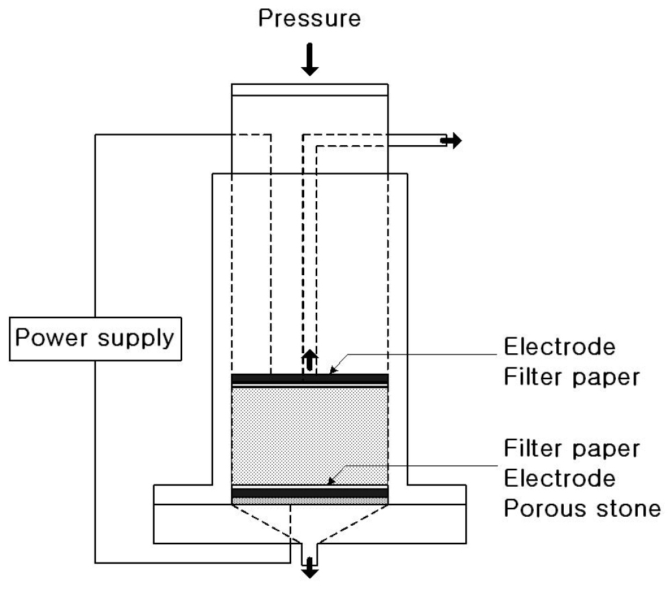
The batch-type experimental apparatus used for electro-osmotic dewatering under a pulse electric field used during this study is shown in Fig. 1. The apparatus is constructed of acrylic resin for insulation and consists of a dewatering vessel, a piston for mechanical expression, filter media, and electrodes. A pair of filter sheets of paper, and perforated carbon plates set in contact with each paper sheet, were used as the filter media and electrodes, respectively. The soil was placed between the two electrodes by a cylindrical piston in which the upper electrode is attached to the bottom, and a pulse electric field was simultaneously applied to the bed. The soil bed was then dewatered electro-osmotically in both the upward and downward directions (Fig. 1).
Testing Procedure
White clay (commercial kaolinite) was used as the experimental material. A white clay-deionized water sample was prepared with uniform water content throughout the bed. Maintaining the applied mechanical pressure, a pulse electric field was subsequently applied to the bed through an electric power generation system, permitting dewatering of the soil through electro-osmosis only. The amount of dewatering and electric current passing through the bed were measured with time. The pH distribution and water content distribution in the direction of the sludge bed height were also measured after dewatering. To compare results under the pulse electric field with those under DC, an experiment under continuous DC was performed similarly. In this case, as the white clay was negatively charged, the upper electrode was used as an anode, whereas the lower one was the cathode. The soil was electro-osmotically dewatered downward (Fig. 1).
Electro-Osmotic Pulse System
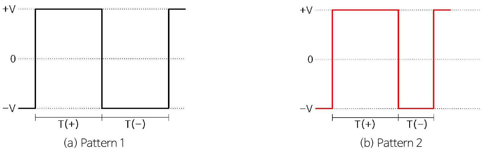
The electro-osmotic pulse (EOP) system consists of a positive voltage pulse, a negative voltage pulse, and a period when no voltage is applied. Fig. 2 shows an example waveform for the EOP system. The positive voltage pulse has the longer interval, and the negative voltage pulse has the shorter interval. Consequently, the pore fluid moves in one direction on average.
Currently, the reasons for the increased performance of the EOP system over a standard DC electro-osmosis for the dewatering of soils are not well understood. However, it is speculated that a change in polarity results in a reversal of some of the chemical reactions that occur during electrolysis. As a result of these effects, undesirable side effects, such as the production of acid and increased corrosion of electrodes are avoided. In addition, the use of a pulse sequence might prevent the soil from becoming too dry.
Results and Discussion
Amount of Dewatering
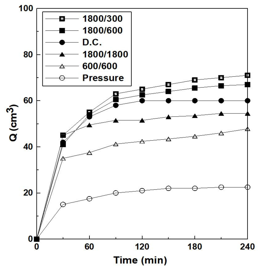
Fig. 3 illustrates temporal variations in the dewatered amount, Q, with reversal period as a parameter. The experimental conditions of the pulse show a constant voltage of 50 V. Q increases with increasing reversal time, approaching the dewatered amount obtained under DC conditions. Short negative direction times (1,800/600 seconds, 1,800/300 seconds) demonstrate that the final dewatered amounts at the end of dewatering are much greater than those under DC conditions. These results suggest that the marked increase in electrical contact resistance between the electrode and soil bed was somewhat reduced because the water in the bed under pulse conditions moved periodically in both the upward and downward directions.
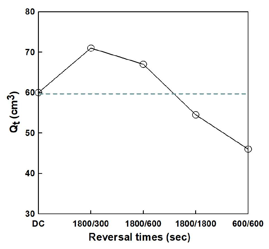
The relationship between the final (end-of-experiment) values of dewatered amounts (Qt), and reversal times during the applied pulse regime is shown in Fig. 4. The values of Qt increase approximately linearly with increasing reversal time, whereas for short negative times, Qt becomes larger than that under DC conditions. Accordingly, electro-osmotic dewatering under a pulse can enhance the dewatered amount compared with DC, and is effective for reducing the water content uniformly throughout the bed.
Temporal Variations in Electric Current
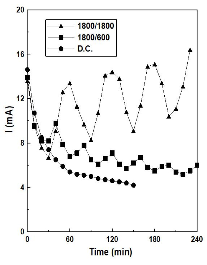
Fig. 5 shows temporal variations in electric current, I, passing through the sludge bed with reversal time as a parameter. Under the DC electric field, I initially decreases rapidly and then decreases gradually with time t. This can be explained in terms of the marked increase in electrical contact resistance, as described above. In contrast, I under a pulse shows a tendency to increase gradually with t with increasing reversal time.
Final pH and Water Content Distribution in the Soil Bed
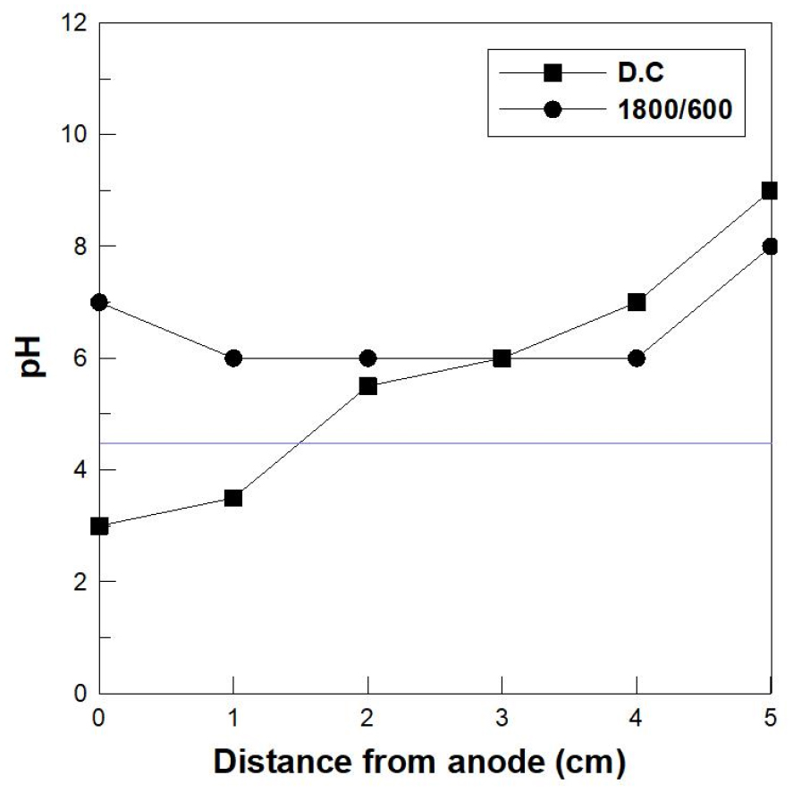
The soil bed after dewatering was cut horizontally into four small pieces in the vertical direction of the bed, and the pH of the surface and water content of each piece were measured using litmus paper, and weighed after drying. Fig. 6 shows the final distribution of pH. The initial pH throughout the bed was approximately 4.5. The pH values in the upper part of the bed under DC were acidified, whereas those in the lower part were alkalified. The pH values under the pulse electric field were somewhat alkalified in both the upper and lower parts but were overall more uniform throughout the bed compared with DC conditions. However, the water content under DC decreased drastically near the top of the bed, whereas the distribution of water content under the pulse electric field tended to be reduced uniformly throughout the bed.
Conclusions
The application of a pulse electric field to improve electro-osmotic dewatering was investigated experimentally. The experiments were carried out for electrode polarity reversals of the pulse under constant voltage conditions. The experimental results under a pulse electric field were compared with those under a continuous DC electric field. The following results were obtained:
(1) Electro-osmotic dewatering under the electric pulse system is capable change in voltage pulse directions.
(2) The final dewatered amount under the electric pulse system for a particular duration of negative voltage pulse is greater than that under DC conditions.
(3) The application of a pulsed electric field can reduce the marked increase in the electrical contact resistance between the electrode and soil caused by DC.
(4) Under pulse conditions, the local pH in the soil bed does not change significantly, and the hindrance for dewatering caused by DC is reduced, making it possible to decrease the water content throughout the bed effectively.
(5) The pulse system can be used to enhance drainage from a water storage facility during an extreme drought period.
